AxField
Expert Member
- Joined
- Apr 30, 2009
- Messages
- 1,647
- Reaction score
- 1,749
I've had a few people ask about how I integrated my Paradox Alarm with Home Assistant. There's a few ways to do it, but I wanted the most elegant and compact (hardware wise) solution for me, without paying stupid money for an IP150 module which is still very limited, especially with the newer firmware. I also wanted it to be self contained and run on my WiFi network, with all the other IoT devices I have running.
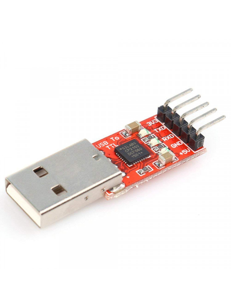
Most of the software work has been done by the authors of PAI, but for some reason there's no tutorial to do it the way I wanted to do it using a Pi Zero W. As a proof of concept, I eventually got it going using a Paradox USB interface (which is nothing other than a fancy USB to TTL interface), which I had laying around that I used to program my Panel using Babyware.

I had this running for a few weeks to make sure the Pi Zero is suitable for the purpose (seeing as it's not on the PAI recommended list) and it worked like a dream. Only issue is that it's not very elegant nor neat. As it was tested, you're going from Paradox TTL to USB, into the USB port of the Pi, then back to a virtual Serial port into PAI. A better way to do it would be to go directly from the Paradox serial port into the Pi. Only issue is that the Paradox TTL Serial is at 5V and the Pi Serial is 3V3 (and I checked, the PI I/O is not 5V tolerant).
After some messing about, I came up with the below wiring diagram. I'm using a 12V to 5V DC to DC converter to power the Pi directly off the 12V Aux pin1 on the Paradox Serial connector.
I used this one, but any suitable board will work:
https://www.robotics.org.za/D1-POWER?search=d1 power shield
For level shifting the 5V TTL of the Paradox Serial port to the 3V3 TTL of the Pi Zero, I used this. It's a 4 channel unit (you only need 2 channels), but it's all they had in stock:
https://www.robotics.org.za/BOB-12009?search=4 Channel - Logic Level Converter Bi-Directional
This is the way it's all connected:
This is how it's all wired up, as per the above schematic. It's not pretty, but it's solid and compact. I sandwiched a piece of plastic between the PI and the two boards, with a little hot glue to keep it all together:

I recently got a 3D printer and was itching to use it for something other than printing Benchies. It's actually the first time I designed anything in 3D, so just excuse the lack of any flair

And done, with the lid in place as well. Still battling to get my bed leveling perfect on the printer, but it's functional at least.

Last but not least, it's working perfectly with Home Assistant.

In as much as setting it all up on the Pi Zero W, I'm running the latest Raspberry Pi OS, 32bit Lite (as I don't need a GUI because it's running headless in the panel).
Setting up PAI, I followed this guide:
https://github.com/ParadoxAlarmInterface/pai/wiki/Manual
Because you're running a Pi Zero W, there's some additional step you need to take in order to enable the serial port on the GPIO pins, it's not enabled by default on the Pi Zero W as would be the case with other versions.
I'm going to assume you know your way around Linux, using Nano as a configuration editor and how to use Putty to SSH into the Pi. Things in Italic is what you need to enter
Enable hardware UART PL011 port:
- Disable built in BT module
sudo nano /boot/config.txt
Add dtoverlay=pi3-miniuart-bt to end of file, save and reboot
- After reboot, check if ttyS0 is now available. This shows that BT is switched off and that ttyAMA0 is available on GPIO. If it doesn't return ttyS0 then ttyAMA0 is still mapped internally to BT device.
ls -lsa /dev/serial*
0 lrwxrwxrwx 1 root root 7 Sep 26 12:12 /dev/serial0 -> ttyAMA0
0 lrwxrwxrwx 1 root root 5 Sep 26 12:12 /dev/serial1 -> ttyS0
- Disable Console Messages over UART
sudo nano /boot/cmdline.txt
Remove console=serial0,115200 at start of file, save and reboot
Once the above is done, you need to configure PAI to send Panel updates using MQTT (I prefer this method over directly integrating with HA, as MQTT is more universal for non HA implementations).
See below my configuration, yours would probably be very similar to mine. I've only included the changes to the example pai.conf file
CONNECTION_TYPE = 'Serial' # Serial or IP
SERIAL_PORT = '/dev/ttyAMA0' # Pathname of the Serial Port
SERIAL_BAUD = 9600 # 9600 for SP/MG. For EVO: Use 38400(default setting) or 57600
KEEP_ALIVE_INTERVAL = 10 # Interval between status updates
POWER_UPDATE_INTERVAL = 60 # Interval between updates of the battery, DC and VDC voltages
PUSH_POWER_UPDATE_WITHOUT_CHANGE = True # Always notify interfaces of power changes
PUSH_UPDATE_WITHOUT_CHANGE = False # Always notify interfaces of all changes
MQTT_ENABLE = True # Enable MQTT Interface
MQTT_HOST = 'yourmqttbroker' # Hostname or address
MQTT_PORT = 1883 # TCP Port (TLS port if MQTT_TLS_CERT_PATH is set)
MQTT_USERNAME = 'yourmqttbrokerusername' # MQTT Username for authentication
MQTT_PASSWORD = 'yourmqttbrokerpassword' # MQTT Password
MQTT_RETAIN = True # Publish messages with Retain
MQTT_REPUBLISH_INTERVAL = 60 * 60 * 12 # Interval for republishing all data
MQTT_BASE_TOPIC = 'paradox' # Root of all topics
MQTT_ZONE_TOPIC = 'zones' # Base for zone states
MQTT_PARTITION_TOPIC = 'partitions' # Base for partition states
MQTT_BUS_TOPIC = 'buses' # Base for buses states
MQTT_MODULE_TOPIC = 'bus-module' # Base for bus module states
MQTT_SYSTEM_TOPIC = 'system' # Base for panel states
MQTT_USER_TOPIC = 'users' # Base for user states
MQTT_EVENTS_TOPIC = 'events' # Base for events
MQTT_CONTROL_TOPIC = 'control' # Base for control of other elements (ROOT/CONTROL/TYPE)
MQTT_DEFINITIONS_TOPIC = 'control' # Base for definitions
MQTT_HOMEASSISTANT_DISCOVERY_PREFIX = 'homeassistant'
MQTT_OUTPUT_TOPIC = 'outputs'
MQTT_DOOR_TOPIC = 'doors'
MQTT_KEYPAD_TOPIC = 'keypads'
MQTT_STATES_TOPIC = 'states'
MQTT_NOTIFICATIONS_TOPIC = 'notifications'
MQTT_SEND_PANIC_TOPIC = 'panic'
MQTT_PUBLISH_RAW_EVENTS = True
MQTT_INTERFACE_TOPIC = 'interface'
MQTT_TOGGLE_CODES = {}
MQTT_USE_NUMERIC_STATES = False # use 0 and 1 instead of True and False
MQTT_PUBLISH_COMMAND_STATUS = True # Publish command statuses to MQTT
MQTT_COMMAND_STATUS_TOPIC = "command_status"
MQTT_HOMEASSISTANT_AUTODISCOVERY_ENABLE = True
That should be it. It seems a little involved but the above should get you going in no time
Most of the software work has been done by the authors of PAI, but for some reason there's no tutorial to do it the way I wanted to do it using a Pi Zero W. As a proof of concept, I eventually got it going using a Paradox USB interface (which is nothing other than a fancy USB to TTL interface), which I had laying around that I used to program my Panel using Babyware.
I had this running for a few weeks to make sure the Pi Zero is suitable for the purpose (seeing as it's not on the PAI recommended list) and it worked like a dream. Only issue is that it's not very elegant nor neat. As it was tested, you're going from Paradox TTL to USB, into the USB port of the Pi, then back to a virtual Serial port into PAI. A better way to do it would be to go directly from the Paradox serial port into the Pi. Only issue is that the Paradox TTL Serial is at 5V and the Pi Serial is 3V3 (and I checked, the PI I/O is not 5V tolerant).
After some messing about, I came up with the below wiring diagram. I'm using a 12V to 5V DC to DC converter to power the Pi directly off the 12V Aux pin1 on the Paradox Serial connector.
I used this one, but any suitable board will work:
https://www.robotics.org.za/D1-POWER?search=d1 power shield
For level shifting the 5V TTL of the Paradox Serial port to the 3V3 TTL of the Pi Zero, I used this. It's a 4 channel unit (you only need 2 channels), but it's all they had in stock:
https://www.robotics.org.za/BOB-12009?search=4 Channel - Logic Level Converter Bi-Directional
This is the way it's all connected:
This is how it's all wired up, as per the above schematic. It's not pretty, but it's solid and compact. I sandwiched a piece of plastic between the PI and the two boards, with a little hot glue to keep it all together:
I recently got a 3D printer and was itching to use it for something other than printing Benchies. It's actually the first time I designed anything in 3D, so just excuse the lack of any flair
And done, with the lid in place as well. Still battling to get my bed leveling perfect on the printer, but it's functional at least.
Last but not least, it's working perfectly with Home Assistant.
In as much as setting it all up on the Pi Zero W, I'm running the latest Raspberry Pi OS, 32bit Lite (as I don't need a GUI because it's running headless in the panel).
Setting up PAI, I followed this guide:
https://github.com/ParadoxAlarmInterface/pai/wiki/Manual
Because you're running a Pi Zero W, there's some additional step you need to take in order to enable the serial port on the GPIO pins, it's not enabled by default on the Pi Zero W as would be the case with other versions.
I'm going to assume you know your way around Linux, using Nano as a configuration editor and how to use Putty to SSH into the Pi. Things in Italic is what you need to enter
Enable hardware UART PL011 port:
- Disable built in BT module
sudo nano /boot/config.txt
Add dtoverlay=pi3-miniuart-bt to end of file, save and reboot
- After reboot, check if ttyS0 is now available. This shows that BT is switched off and that ttyAMA0 is available on GPIO. If it doesn't return ttyS0 then ttyAMA0 is still mapped internally to BT device.
ls -lsa /dev/serial*
0 lrwxrwxrwx 1 root root 7 Sep 26 12:12 /dev/serial0 -> ttyAMA0
0 lrwxrwxrwx 1 root root 5 Sep 26 12:12 /dev/serial1 -> ttyS0
- Disable Console Messages over UART
sudo nano /boot/cmdline.txt
Remove console=serial0,115200 at start of file, save and reboot
Once the above is done, you need to configure PAI to send Panel updates using MQTT (I prefer this method over directly integrating with HA, as MQTT is more universal for non HA implementations).
See below my configuration, yours would probably be very similar to mine. I've only included the changes to the example pai.conf file
CONNECTION_TYPE = 'Serial' # Serial or IP
SERIAL_PORT = '/dev/ttyAMA0' # Pathname of the Serial Port
SERIAL_BAUD = 9600 # 9600 for SP/MG. For EVO: Use 38400(default setting) or 57600
KEEP_ALIVE_INTERVAL = 10 # Interval between status updates
POWER_UPDATE_INTERVAL = 60 # Interval between updates of the battery, DC and VDC voltages
PUSH_POWER_UPDATE_WITHOUT_CHANGE = True # Always notify interfaces of power changes
PUSH_UPDATE_WITHOUT_CHANGE = False # Always notify interfaces of all changes
MQTT_ENABLE = True # Enable MQTT Interface
MQTT_HOST = 'yourmqttbroker' # Hostname or address
MQTT_PORT = 1883 # TCP Port (TLS port if MQTT_TLS_CERT_PATH is set)
MQTT_USERNAME = 'yourmqttbrokerusername' # MQTT Username for authentication
MQTT_PASSWORD = 'yourmqttbrokerpassword' # MQTT Password
MQTT_RETAIN = True # Publish messages with Retain
MQTT_REPUBLISH_INTERVAL = 60 * 60 * 12 # Interval for republishing all data
MQTT_BASE_TOPIC = 'paradox' # Root of all topics
MQTT_ZONE_TOPIC = 'zones' # Base for zone states
MQTT_PARTITION_TOPIC = 'partitions' # Base for partition states
MQTT_BUS_TOPIC = 'buses' # Base for buses states
MQTT_MODULE_TOPIC = 'bus-module' # Base for bus module states
MQTT_SYSTEM_TOPIC = 'system' # Base for panel states
MQTT_USER_TOPIC = 'users' # Base for user states
MQTT_EVENTS_TOPIC = 'events' # Base for events
MQTT_CONTROL_TOPIC = 'control' # Base for control of other elements (ROOT/CONTROL/TYPE)
MQTT_DEFINITIONS_TOPIC = 'control' # Base for definitions
MQTT_HOMEASSISTANT_DISCOVERY_PREFIX = 'homeassistant'
MQTT_OUTPUT_TOPIC = 'outputs'
MQTT_DOOR_TOPIC = 'doors'
MQTT_KEYPAD_TOPIC = 'keypads'
MQTT_STATES_TOPIC = 'states'
MQTT_NOTIFICATIONS_TOPIC = 'notifications'
MQTT_SEND_PANIC_TOPIC = 'panic'
MQTT_PUBLISH_RAW_EVENTS = True
MQTT_INTERFACE_TOPIC = 'interface'
MQTT_TOGGLE_CODES = {}
MQTT_USE_NUMERIC_STATES = False # use 0 and 1 instead of True and False
MQTT_PUBLISH_COMMAND_STATUS = True # Publish command statuses to MQTT
MQTT_COMMAND_STATUS_TOPIC = "command_status"
MQTT_HOMEASSISTANT_AUTODISCOVERY_ENABLE = True
That should be it. It seems a little involved but the above should get you going in no time