Let's design our own UPS

This particular BMS that you linked is a 3S one. Doesn't seem to be options, so you'll need to use 3 cells in series.

Does this mean I can do as many parallel as I want as long as I stick to 3 cells in series?

Becuase then this might work, ie I am after capacity (parallel), I can make this work from any voltage using the buck/boost converter.

So ideally I would have done say 2S so (3.7v x 2 = 7.4v), but then 6 parallel

so

7.4v and 15 600 mah
= =
= =
= =
= =
= =
= =

OR
1S and 12 parallel

3.7v and 31 200 mah
=
=
=
=
=
=
=
=
=
=
=
=

Thoughts?
 
Does this mean I can do as many parallel as I want as long as I stick to 3 cells in series?
Theoretically yes, but practically no.

You could probably use two or three, but you'll need to look at things like their charging current. If the cells can each charge at (for argument's sake) 10A, and your BMS is limited to 20A, then three in parallel will each only get 20/3=6.67A charging current. Which is probably fine... but if you go mad and put ten in parallel then they'll each only get 2A of charging current which will result in charging times being too long. You won't want to run your charging circuitry at max current for extended periods of time unless you carefully work out the heat dissipation.

Regarding your calculations, yes, 2S6P has the same amount of energy as 1S12P (in terms of the watt hours (Wh) which you get by multiplying the voltage by the number of Ah). And yes, in theory you can be relatively independent of what the precise input voltage is, due to the availability of buck-boost converters. But they are not perfectly efficient. So you may find that boosting from 3.7V to 5V, you'll lose (e.g.) 10% in the process, while bucking from 7.4V to 5V may only have 5% of losses. So your capacity goes further due to your circuitry being more efficient.

(I'm just making the numbers up, trying to put across the concepts behind. Part of the job of the engineer is to look at the requirements, and figure out from the specs of the individual parts, what the best way to meet those requirements is.)
 
Why would you need pure sine to power a router/laptop that has an SMPS?

Because it allows one to plug in any type of small load making the system more flexible. 10W desk fan, audio equipment/powered speakers, etc.
Not everything uses a SMPS and some people may want to power other types of small loads during load shedding other than just an ONT, router or laptop.
 
Because it allows one to plug in any type of small load making the system more flexible. 10W desk fan, audio equipment/powered speakers, etc.
Not everything uses a SMPS and some people may want to power other types of small loads during load shedding other than just an ONT, router or laptop.
You do have to set limits somewhere though. You can't build something that is all things to all men.
 
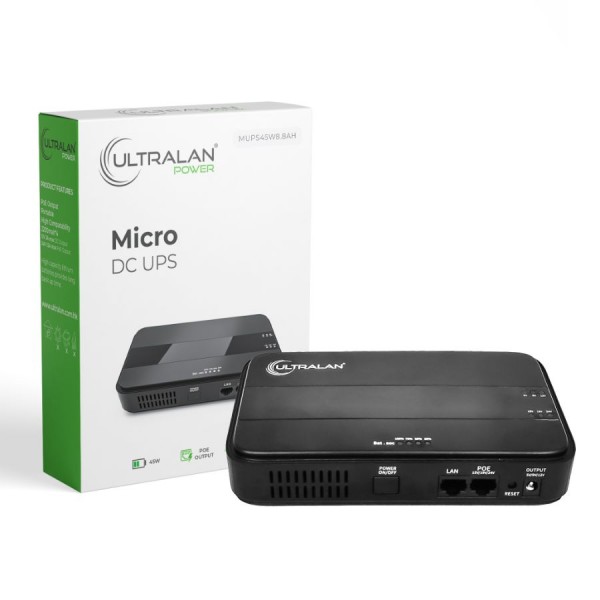
This is actually pretty nice, but only one output at a time.

Yes, more of a "one per device" type UPS. It's 32Wh which is probably only enough to power an ONT and Wifi router for around 1.5 to 2 hours so it's a bit on the light side in my opinion. R499.99/32.56Wh = R15.36/Wh

The Ratel 860p (65.12Wh) is only a bit more expensive at R19.73/Wh (Communica), has a plethora of output ports and voltages as well as a solar input port.
 
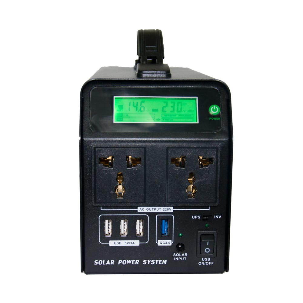
I have brought two of these:

Not as nice as my ecoflow delta, but only 20% the price for 40% the battery capacity.

The Immediate downside is it is modified sinewave, so it's not compatible with all equipment. The second issue is a really crappy quality and noisy 4cm cooling fan. I retrofitted in a higher quality 6cm fan and now they are silent enough for domestic use.

But I think the format could work very well. Make it a bit taller to accommodate a pure sinewave inverter and expand the DC. It seems to have a 12v (2x 6v) configuration of 18650 lithium iron phosphate batteries. About 400wh's worth.

Here are some photos I took before retrofitting it:
IMG_20210128_115055.jpg
IMG_20210128_115011_1.jpg
IMG_20210128_115000.jpg
 
The blocker,

I have no idea how to have this run off mains when mains is available and battery when mains is off and mains again when mains is back, automatically, uninterrupted.

Until we can solve that, I can't go further.
 
The blocker,

I have no idea how to have this run off mains when mains is available and battery when mains is off and mains again when mains is back, automatically, uninterrupted.

Until we can solve that, I can't go further.
I am building my own backup power.Got inspired after watching Will Prose's series of milk crate videos, I am also adding DC backup to my build.

Youtube link

Voltage flows from the higher to the lower... so if you had a battery of 4s that is on 12.8V and you connect a charger of 12.8V then very little current would flow to the battery, if you increase it to 12.9 then a lot more current would flow. So effectively you could pick a voltage that is 90% charge then leave it connected to the batteries, but the routers/ONT/NAS would be powered from this "float" voltage pulling all the current it needs, should the current demand cause the voltage to dip (eg some idiot plug in a usb heater fan) to eg. 12.6V then the batteries will do their bit and supply current to keep the system in balance. Should eskom happen then the batteries will take over and carry the full load.

Personally I would keep my batteries at about 90% charge as this seems to be the sweet spot. So I started by building as 12V (4s) with a BMS (LiFeSO4 50Ah, 160Wh), to keep cells balanced and protected. (Laptops work at 19V so this means I need to boost) I chose 12V configuration as there are lots of bulbs and camping appliances that would work on 12V but I am starting to think that 24V might be the better option. Also my ONT and router requires 12V.

To some degree I am very tempted to buy a ratel and just mod it to work with the bigger battery. (Using my own charging circuit).

Mains connected to charger (charging at battery 90% voltage) which is connected to both bateries and DC Buck, DC Buck supplies power to router.
 
Last edited:
He's got another video about the same thing where he explains it a bit more.


Yeah I saw that, but it still pretty much just something largely along the lines of this :


So I mean good on the guy for building something himself, its just one of those cases (for me at least) of solving a "problem" that has already been solved really.
 
Yeah I saw that, but it still pretty much just something largely along the lines of this :


So I mean good on the guy for building something himself, its just one of those cases (for me at least) of solving a "problem" that has already been solved really.

I am really interested in getting something like this, but I am a complete noob with these things.

Would I be able to power my CPE and my router with this?
 
I am really interested in getting something like this, but I am a complete noob with these things.

Would I be able to power my CPE and my router with this?

In theory you should be able to yes. I would just check what the power brick for the CPE outputs, and make sure it matches.
 
In theory you should be able to yes. I would just check what the power brick for the CPE outputs, and make sure it matches.
It depends on the voltage. If your CPE and Router are both 9v or both 12v then it will. Personally though, I'd go with the Ratel 418. Same price but has more ports. And, stock is available.
 

Attachments

  • IMG_20210429_114723.jpg
    IMG_20210429_114723.jpg
    43.1 KB · Views: 35
Still want to continue with this project, my challenge is the power path - ensure the batteries are only used when the AC power is out.
 
Top
Sign up to the MyBroadband newsletter
X